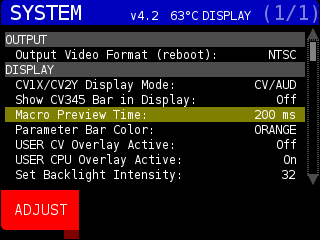
Pressing the SYSTEM button opens the SYSTEM page. In the top center of the screen is the active STRUCTURE version (v4.2 in the image below). Next is a reading from the CPU’s internal temperature sensor.
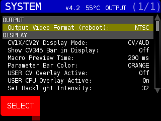
OUTPUT Section:
Output Video Format (reboot): Change between NTSC and PAL video output. STRUCTURE will need to be rebooted to complete the change.
DISPLAY Section:
CV1X/CV2Y Display Mode: Show CV, AUD, or both (CV/AUD) in DISPLAY MENU, MODULATORS page.
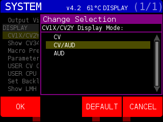
Use the ENCODER knob to choose, press OK soft key to change what is displayed, press the DEFAULT soft key to change to CV/AUD, and press CANCEL soft key to exit the Change Selection window. The CV is represented as a line and AUD is represented by solid green and orange boxes:
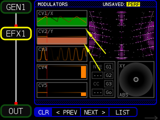
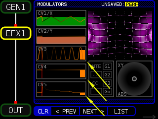
Show CV345 Bar in Display: Show or hide orange boxes in DISPLAY MODULATORS page that relate to the incomming value:
Macro Preview Time: Change how long the pop-up window that shows the MACRO values stays on screen before closing. When Macro Preview Time is highlighted, you can press the ADJUST soft key:
Which will open the Change Value pop-up window:

Use the ENCODER knob to set how long the MACRO chanage pop-up window is shown on screen. When you adjust a MACRO knob on the front page, a pop-up window shows the current value of the MACRO. In the above screen capture the MACRO 3 knob (assigned to Saturation) is being turned.
Parameter bar color: Change the color of the bar in the DISPLAY page, PARAMETERS menu. Use the ENCODER knob to choose a new color and press the OK soft key. Press the DEFAULT soft key to change the value back to CYAN and press the CANCEL soft key to close the Change Selection window without making any changes.

Here the color has been changed to orange:

USER CV Overlay Active: Show or hide CV when pressing USER button.
USER CPU Overlay Active: Show or hide CPU when pressing USER button.
Set Backlight Intensity: Sets LCD backlight brightness.
Show LMH in Modulators: Show the incoming Low/Medium/High volume in DISPLAY:MODULATORS
LMH Bar Transparency: Transparency of the bar
You can see the LMH bars int eh CV1/X Modulator window:

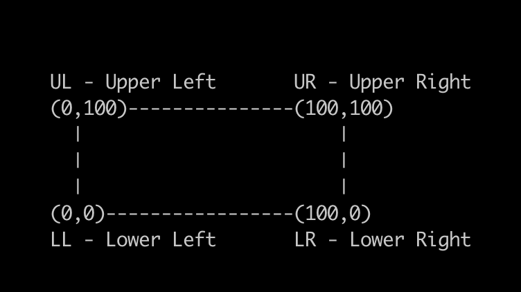
These setting allow you to change the corners of the output, for when you project on non-parallel surfaces:
Reset Screen Mapping: Press the OK soft key to remote all Screen Map values to defaults
Screen Map LL X: Lower Left X (horizontal) position
Screen Map LL Y: Lower Left Y (vertical) position
[…]
These refer to the corners of the screen with (0,0) in the lower left corner and (100,100) in the upper right:
CLIPS section
Max Clip Length (0=no limit): Set maximum number of frames for a CLIP to use. Set to zero to load up to the maximum number of frames. You can have 400 Frames of 640×480 video or 1600 frames of 320×240 video. The clips must be encoded as MJPEG A, One Field, No Interlace, and No audio.
Clip Resolution: Use the ENCODER to choose 240 for 320×240 resolution clips or 480 for 640×480 resolution clips. STRUCTURE can not mix clips of different resolutions.
Load Clips: Toggle between loading video clips on startup or not. If no video files are found on the front SD CARD in the clips/ directory, the default clips will be loaded.
PERF section
Autosave Performance Settings: When any setting that would be saved to the PERFORMANCE is made, STRUCTURE will auto-save the current PERFORMANCE. This might cause a slight hiccup in video out for the I/O operation and is turned OFF by default. You can always save the current PERFORMANCE settings by pressing the PERF button and pressing the SAVE PERF soft key.
Performance to Load on Start: Choose the PERFORMANCE that is loaded on start. Defaults to PERF001 if no other PERFORMANCES are found.
Load Preset on Performance Load: Toggle between loading a specific PRESET when a PERFORMANCE is loaded or not.
Preset #: The PRESET (1 to 16) to be loaded.
Fade In/Out Time: When changing PRESETS, set the number of frames to fade to black, load new PRESET and fade up. This attempts to mask the brief pause of video output when loading and compiling a new NODE SET and the FRAG shaders and other assets that are used by the NODES.
Preset Fade: Turn on to fade between switching presets, turn off to load preset immediately.
Random ALL NODES Fade: Fade out before randomizing all NODES
Random NODE SET Fade: Fade out before randomizing NODE SET
Nodeset Filter Type: For use with the NODE SET page. Set FILTER logic as AND or OR.
For example, filtering for GEN1 and EFX1 with filter type AND will only show NODE SETS with both NODES. With filter type OR, NODE SETS like VID-EFX1 would show up because they satisfy one of the NODE types filtered.
Bank Prev/Next wraps: Set if previous/next PRESET stays in the same BANK or goes to the previous/next BANK. For example if this is set to OFF, when you are at BANK 1, PRESET 16, pressing Next Preset, Structure will load BANK 2, PRESET 1. If set to ON, it would stay in BANK 1 and load BANK 1, Preset 1.
Preset Prev/Next behavior: Determines what happens when using previous and next preset ACTIONS. Pressing the SELECT soft key brings up a list of options :
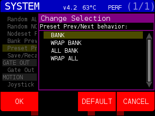
BANK : Prev and Next preset only goes between the current BANK presets 1 through 16
WRAP BANK: Prev and Next preset cycle through presets. Pressing Next on BANK 1, PRESET 16 will load BANK 1, PRESET 1. Pressing Prev on BANK 1, PRESET 1 will load BANK 1, PRESET 16
ALL BANK: Prev and Next will go from BANK 1, PRESET 1 to BANK 4, PRESET 16 (excluding any empty presets)
WRAP ALL: Prev and Next will go from BANK 4, PRESET 16 to BANK 1, PREST 1 and vice versa.
Save/Recall Nodeset Filter in PERF : Auto save NODE SET filter settings when changed and auto load FILTER settings when Performance is loaded.
GATE OUT Section
Gate Out Mode : 0=Norm – gate out trigger is sent after video frame renders, timing varies depending on frame render time. Values 1 to 240 – number of seconds between GATE OUT triggers.
MOTION Section
Joystick Slew (0=None): Amount of “drag” on the JOYSTICK on position change. Set to zero for immediate follow, larger values increase the amount of time the values take to catch up with the JOYSTICK position for smoother movement
Joystick Max Value: Limit maximum value of the JOYSTICK. Affects both X and Y positions and values.
MIDI Section
Global MIDI note Channel (0=omni): Listen to incoming MIDI data on all channels if 0, otherwise only listen on specified MIDI channel (1-16)
2D MOD MIDI note Channel (0=omni): for 2D NODE programs that respond to external modulations (file names start with ’emod’ – like emodTextBits)
MIDI CC Chanel (0=omni): Listen to incoming MIDI continuous controller (CC) data on all channels if 0, otherwise only listen on specified MIDI channel (1-16)
MIDIA – MIDID MOD Channel (0=omni): If 0, process all incoming MIDI note data on all channels, otherwise only on the specified MIDI channel (1-16). The incoming MIDI note is converted to values 0 to 11 then divided by 11 to get a value between 0.0 and 1.0.
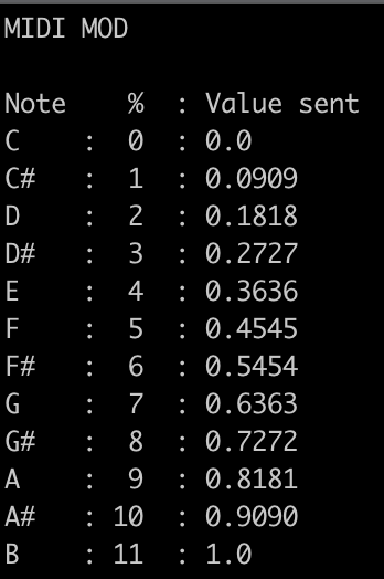
So, C3, C4, C5, etc all send the same value. Modulating MIDI notes like this allows for 12 ‘settings’ that you can jump back and forth between on a MIDI keyboard or drum pad.
STARTUP Section
Randomize Shaders on Startup: Send a RANDOM action to all NODES on start up.
Recall Override on Startup: If overrides to the DEFAULT NODE parameters are found, automatically enable them. The NODE will have a purple background in the NODE DISPLAY diagram when override is enabled. Overrides are set from the MOD SOURCES page.
SDCARD Section
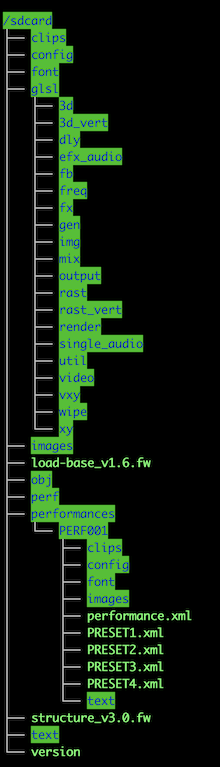
Create Directory STRUCTURE on SDCARD: Press to create the directory structure on the FRONT SD CARD. You can place custom Shaders, images, video clips, 3-D objects, fonts, and text files in designated directories and use them with their associated NODES. It will create the following directory structure:
Format SDCARD for STRUCTURE: This option will format the front SDCARD as FAT32 for use with STRUCTURE. An alert will pop up if the card is already formatted correctly.
SYSTEM Section
System Fan: Turn the back fan on or off. The default is OFF.
UTILITY Section
Calibrate Joystick: Selecting this option will allow you to calibrate the JOYSTICK. The Center Capture window is used ensure a proper ‘dead zone’ for the JOYSTICK so micro-movements are not interpreted as action movement. You can see the X- and Y-values showing the constant changes.
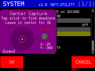
The white dot of the JOYSTICK should be inside the red circle. Move the JOYSTICK all the way in a random direction, then release it so it comes back to center. You can use the ENCODER knob to increase the size of the red circle if needed. Press the OK soft key to open the Range Capture window:
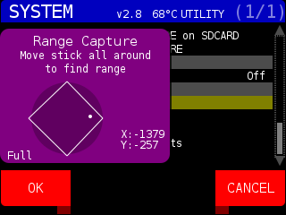
Move the JOYSTICK around the perimeter of the JOYSTICK holder to get a full diamond like above. Pressing the OK soft key will close the window and return to the SYSTEM page. JOYSTICKS are calibrated before they are shipped out.
Open Firmware Menu: Selecting this option and pressing the OK soft key will open a warning asking, ‘This action will discard all unsaved changes, continue?”
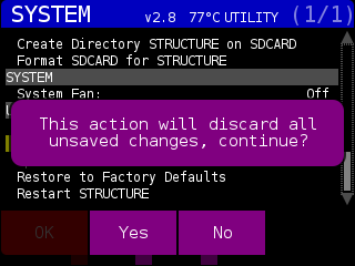
Pressing the YES soft key will open the FIRMWARE UPDATE TOOL (part of the STRUCTURE SYSTEM MENU).
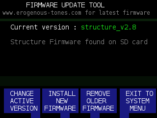
This tool shows the current version of the STRUCTURE firmware running. If there are any STRUCTURE firmware updates on the FRONT SD CARD, the message ‘Structure Firmware found on SD card” will be displayed. Press the CHANGE ACTIVE VERSION soft key to choose a different version of STRUCTURE from the front SD CARD. Always remember to check https://erogenous-tones.com/structure-firmware/ for the latest STRUCTURE firmware.

Use the ENCODER to choose a different firmware version of STRUCTURE and press the SELECT soft key to change the active version. Press the BACK soft key to return to the FIRMWARE UPDATE TOOL main menu. Press the INSTALL NEW FIRMWARE to load a different firmware from the FRONT SD CARD.
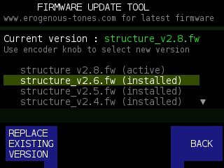
Firmware files found on the FRONT SD CARD will be listed on this page. If the firmware has been installed onto STRUCTURE, it will have (installed) after the firmware name. The running version of the firmware is denoted by (active). If you select the active firmware, and you still have the structure_v?.?.fw file on the FRONT SD CARD, you can re-install the firmware by pressing the REWRITE ACTIVE VERSION soft key. If you select a previously installed firmware, you will press the REPLACE EXISTING VERSION soft key to change versions.
To remove installed versions of the STRUCTURE firmware, you can press the REMOVE OLDER FIRMWARE soft key. This will remove the firmware from the internal storage. It does not remove firmware files from the FRONT SD CARD. Pressing the EXIT TO SYSTEM MENU soft key will take you to the STRUCTURE SYSTEM MENU and display the currently loaded software version.
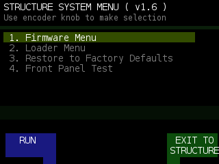
As you can see, the Firmware Menu was a sub-program of the STRUCTURE SYSTEM MENU. On the top line, you see the currently installed version. Use the ENCODER konb to choose a menu option and press the RUN soft key to run it.
1. Firmware Menu: load the FIRMWARE UPDATE TOOL. This is where you upgrade STRUCTURE to the newest version. This is discussed above at LOAD FIRMWARE MENU.
2. Loader Menu: Pressing the RUN soft key will open the LOADER MENU UPDATE TOOL
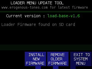
This is where you would load new load-base firmware. STRUCTURE shipped with version 1.6 and we have not released an update. If we do, the software will be available at http://www.erogenous-tones.com. The process is the same as updating STRUCTURE firmware.
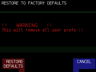
3. Restore to Factory Defaults: This will remove all user PREF (preferences) files.
4. Front Panel Test: This option will run the HARDWARE TEST MODE.
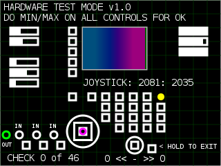
This is the test program we use to verify all buttons, knobs, and the joystick are working correctly before STRUCTURE is sent to our retailers. Activating each control will turn its respective graphic purple. When all 46 tests have completed, it will return to the STRUCTURE SYSTEM MENU. You can hook a 1/8″ to 1/8″ cable from the gate OUT to IN 1 / 2 / 3 to complete the GATE IN tests. Press and hold the ENTER button (to the right of the ENCODER konb) to exit this menu.